AI begins to draw its own hardware: from Monge's graphic geometry, Sketchpad 1963 to GPT-6 Astra
Executive Briefing
Synthesized and verified with gemini-2.0-flash-thinking-exp
“On November 3, 2026 (US time), OpenAI posted a blog post with a rather dry title: "Accelerating engi”
Key Takeaways
- 1.On November 3, 2026 (US time), OpenAI posted a blog post with a rather dry title: "Accelerating engineering for the physical world".
- 2.But inside is a remarkable experiment: they tried letting GPT-6 Astra design a complete hardware device without any engineer directly editing the design.
- 3.Astra set its own functional requirements, drawing the case and internal frames to hold components, choosing electronic components, arranging and wiring the printed circuit board (PCB) to fit the case, then designing the interface and writing firmware so the device could talk to Codex.
On November 3, 2026 (US time), OpenAI posted a blog post with a rather dry title: "Accelerating engineering for the physical world". But inside is a remarkable experiment: they tried letting GPT-6 Astra design a complete hardware device without any engineer directly editing the design. Astra set its own functional requirements, drawing the case and internal frames to hold components, choosing electronic components, arranging and wiring the printed circuit board (PCB) to fit the case, then designing the interface and writing firmware so the device could talk to Codex.
According to R&D World, OpenAI researcher Justin Lin calls this device "Codex pet", a small device with a talk button and screen, helping him check running programming agents without opening his laptop. Two OpenAI members worked on it as a side project in less than a week, and a processing factory produced small sample batches in less than a month. But OpenAI also admitted quite frankly: to put it into production, it still has to go through many rounds of review and editing, because Astra does not always take into account the factory's production limits, tolerances, or the details needed for assembly.
The article also gives some other numbers. Since February, OpenAI hardware and infrastructure teams' model usage, measured in tokens, has increased 23 times. On the BenchCAD 2.0 test, which models 3D reconstructions of parts and assemblies and identifies connections on circuit boards, a newer internal model scored an average of 0.875, compared with 0.594 for the GPT-6 Astra at the highest inference level. OpenAI also announced a research collaboration with Mazda, using Astra to test front-end styles to reduce wind resistance, and expanding its collaboration with Chip Ganassi Racing to turn 3D scanning data of existing parts into editable CAD models and 2D manufacturing drawings.
On the same day, Google also announced Physical-Engineering's Last Exam (PLE), a test set made with Mercor including 85 long-term technical problems in four branches of mechanical, electrical, construction and structural. Each post has an average of 61 files, from PDFs, spreadsheets, emails to 2D CAD drawings and 3D BIM models, just like the resume an engineer would receive in real life. The result: all 14 top models are below 50%, the highest is 48.3%. An interesting point is that the best configuration satisfied 91% of each individual constraint, but only 41.3% of the final product passed all required safety and feasibility tests.
Two announcements on the same day show that AI labs are aiming for a new language: not English or Python, but technical drawing, the language that engineers around the world use to talk to each other and to factories. And this language has a longer history than you think, starting with a French military secret.
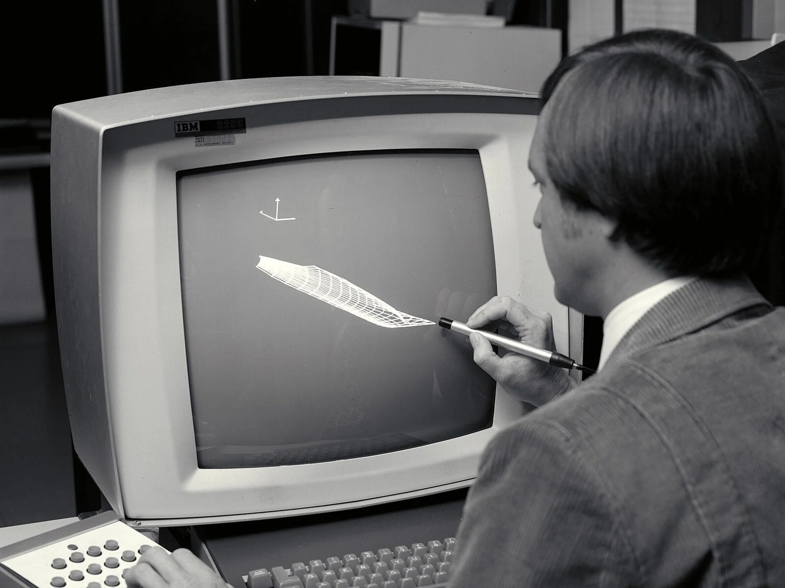
Engineer Paul Kutler uses a light pen to manipulate an IBM 2250 graphics screen at NASA's Ames Research Center, 1973. The light pen and CRT screen were the first tools to bring drawings from paper to a computer
In the mid-18th century, artillery became increasingly powerful, forcing European fortresses to be built in increasingly complex shapes, typically star-shaped forts. A headache for military engineers at that time was "défilement": arranging the height of the walls so that the defenders inside were not subject to direct range fire from high points outside by the enemy. The traditional way is to send soldiers to positions around the fortress to take measurements, or to make lengthy calculations that take up to a week.
According to Wikipedia, a young man named Gaspard Monge (1746–1818), was accepted into the École Royale du Génie engineering school in Mézières as a draftsman. Because he did not come from an aristocratic background, he did not receive the same education as the officer cadets. His drawing skills were praised but his mathematical talent was wasted. After about a year, Monge was assigned to draw up a défilement plan for a fortress. Monge solved the problem with drawings instead of long calculations, built "vision cones" on paper, and finished in just two days. At first, the superiors didn't believe it because it was too fast, but when they checked again, the method was completely correct. From there, Monge developed into an entire field: descriptive geometry, the precise representation of a three-dimensional object by two-dimensional projections on planes perpendicular to each other.
This method was so valuable that France kept it a military secret for many years. Only after the French Revolution did Monge lecture publicly at the École Normale in 1795, and then at the École Polytechnique, where he was a professor of graphic geometry. His lecture was printed into a book in 1799. Those of you who have studied engineering in Vietnam are no stranger to the subjects "Graphics" and "Technical Drawing" with vertical, horizontal, and side projections, which are direct descendants of the Monge method.
Portrait of mathematician Gaspard Monge (1746–1818), father of geometric geometry, the mathematical foundation of technical drawing. Lithograph by François-Séraphin Delpech
Once we have a language, we need a way to clone it. In 1842, British scientist John Herschel introduced the cyanotype printing process, using paper impregnated with a light-sensitive iron compound. The engineer draws the original on tracing paper with Chinese ink, places it on light-sensitive paper, clamps it under glass and then exposes it to the sun for a minute or two. The result was a white line copy on a blue background, what is still called a "blueprint" in English today. According to Wikipedia, this method has been widely used for more than a century to duplicate drawings in construction and industry, to the point that the word "blueprint" is now synonymous with "plan".
During that time, the familiar image of the engineering industry was long drawing rooms with rows of drawing tables, T-rules sliding along the edge of the table, ekes, compasses and pencils. The biggest weakness of hand-drawn drawings is correction: Wikipedia records that if an error is discovered or changes need to be made, the entire drawing must sometimes be redrawn from the beginning. And more importantly, paper drawings have no way to check whether the parts fit together or not.
Two engineers L. C. Karr and H. B. Graves in the technical drawing room at the Ruby Dam project, Washington state, USA, January 1939. Photo: Seattle Municipal Archives
Advertisement
Computers entered the drawing room in the late 1950s. In 1957, Patrick Hanratty at General Electric wrote PRONTO, one of the first commercial numerical control (NC) machine tool programming languages. In 1961 he moved to General Motors, and people often call him "the father of CAD/CAM". Also at GM, a research group in 1958 discovered a huge waste: each step from design sketches, technical designs to detailed drawings used a separate drawing style, each department had its own drawing room, and each time drawings moved from one room to another, it had to be redrawn according to that room's standards, wasting time and causing errors. In 1960, GM joined hands with IBM to create the DAC-1 (Design Augmented by Computer) system, put into use in 1963 and launched to the public in 1964 in Detroit.
But the milestone that the computer graphics world talks about most is Sketchpad, the program that Ivan Sutherland wrote for his doctoral thesis at MIT in 1963, with the instructor being Claude Shannon, the father of information theory, and the board including Marvin Minsky and Steven Coons. Sketchpad runs on Lincoln Laboratory's TX-2 machine, has 64K of 36-bit words, and users draw directly on the screen with a light pen. It allows setting geometric constraints, such as fixing the length of a line segment or the angle between two segments, and using the "original drawing" it is possible to create many copies, editing the original and all copies are changed. These are all concepts that CAD software still uses today. Sutherland received the Turing Award in 1988 for this invention. A fun detail: according to Sutherland himself, the test TX-2's hardware changes regularly, and usually on Wednesdays.
Drawing straight lines and circles is easy, but car bodies or airplane wings are all curves. The problem of representing a curve using an equation was solved almost at the same time by two rival French car companies. In 1959, Citroën mathematician Paul de Casteljau developed an algorithm for calculating stable curves, but his work was kept secret and was not published until the 1980s. Meanwhile, engineer Pierre Bézier at Renault independently found a similar way, used it to design the car body in the UNISURF system and popularized it since the 1960s. As a result, the name "Bézier curve" entered history. Today it is present in every CAD software, in Illustrator, Inkscape, and even in TrueType and PostScript fonts, meaning the very words you are reading on the screen are also drawn with curves by a Renault engineer.
In the aviation industry, in 1977 Avions Marcel Dassault developed a software that added 3D surface rendering capabilities to the CADAM software they were using to design the Mirage fighter. In 1981 it was renamed CATIA and later became the standard of the automobile and aviation industries. As for office workers, the real revolution came in December 1982, when Autodesk launched AutoCAD running on personal computers, instead of having to use expensive mainframes and graphics stations. By 1986, AutoCAD was the most popular CAD software in the world.
Boeing 777 prototype (registration number N7771) in Geneva, Switzerland, September 1995. The Boeing 777 was the first commercial aircraft developed entirely using a computer-aided design process. Photo: Aero Icarus
The pinnacle of this period was the Boeing 777. According to Wikipedia, this was the first commercial aircraft developed entirely in CAD: all drawings were made on CATIA, allowing engineers to "virtual assemble" the entire aircraft on the computer to check for collisions and ensure thousands of details fit together before real assembly. Boeing didn't believe it at first, so it still built a physical model of the nose of the plane for comparison. The match was so good that other physical models were canceled altogether. The 777 became Boeing's first jetliner to not require an expensive full-scale physical model for detailed detailing, and the program is said to keep costs at around $5 billion.
Advertisement
But the tool itself can also be a source of risk. Also according to Wikipedia, in the late 1990s, a complete rewrite of CATIA in version 5 caused incompatibility between versions, contributing to production delays that cost the Airbus A380 program an additional $6.1 billion. Lesson: machines help draw faster, but when the machine misunderstands, the mistakes multiply faster.
Looking back along the way, each wave has done the same thing: shifted repetitive labor to tools, letting humans focus on decisions. Monge replaced the week of calculations with two days of drawing. Blueprint replaces handwriting. CAD replaces the need to redraw the drawing from scratch, then replace the physical model. Hanratty once summed up his software philosophy in one sentence: "the computer writes the program for you". The difference in 2026 is that this time, AI is not just a smarter pen or drawing board, but begins to hold the pen itself, open CAD software, and run simulations itself.
The engineers at OpenAI describe exactly that. Grace Lam says Codex helps them turn 3D designs into manufacturing-ready 2D drawings and set up simulations and finite element analysis (FEA) with much less manual work. Qiong Wang talks about his ambition to have AI "hardware expert teams" that can take a circuit board from concept to Gerber file sent to the factory. And Mazda engineer Akihiro Nakata said that designers often ask "does it have to look like that?" every time the aerodynamics team finds a good shape for the airflow; Astra's exploration and simulation of dozens of variations helped them understand which details were truly important for aerodynamics and where designers still had creative freedom.
However, you should read the numbers with some caution. Techscurrent points out that in the public version of BenchCAD, each run with GPT-6 Astra costs about 11 USD, consumes about 135,000 tokens and takes an average of 62 minutes, while the internal model that scored 0.875 is unnamed and outsiders cannot verify the results. Mazda and OpenAI have not announced any specific drag reduction numbers. And Google's PLE results say the most important thing: 91% correct for each constraint sounds high, but in engineering, a bridge or a pressure vessel only needs one safety condition wrong to fail. That's why PLE only awards points when a design first passes all required safety tests.
The "Codex pet" itself is also a miniature example. The design took less than a week, but what Astra left out were tolerances, factory limits and assembly details, exactly the kind of knowledge that engineers accumulate over many years in the workshop, not contained in books. The story of the Boeing 777 shows that confidence in new tools does not come from advertising, but from building a real aircraft nose model for comparison, and then daring to abandon the remaining models.
For those who are studying or working in engineering, perhaps the most important thing to think about is that the role will shift. The previous generation must be good at holding pencils and T-rules, the next generation is good at manipulating CAD, and the next generation may need to be the best at reading and reviewing drawings made by machines, knowing where the machine is prone to errors and daring to sign and take responsibility. More than 200 years ago, Monge made drawing the common language of engineers. Now machines have begun to speak that language, but the person responsible for what is said is still human.
What do you think of those who work in mechanics, electronics or construction: will CAD drawing AI be an effective assistant, or will it just add proofreading work to engineers?
Source:
OpenAI
,
R&D World
,
Techscurrent
,
Unite.AI
,
Google Cloud Blog (PLE)
,
Wikipedia (Gaspard Monge)
,
Wikipedia (Blueprint)
,
Wikipedia (Technical drawing)
,
Wikipedia (Patrick J. Hanratty)
,
Wikipedia (DAC-1)
,
Wikipedia (Sketchpad)
,
Wikipedia (Ivan Sutherland)
,
Wikipedia (Pierre Bézier)
,
Wikipedia (Paul de Casteljau)
,
Wikipedia (CATIA)
,
Wikipedia (AutoCAD)
,
Wikipedia (Boeing 777)